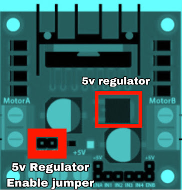
L298N DC Motor driver module with Arduino
there are many motor controllers in this industry L298N is one of them and it's a very popular and useful motor controller
What is l298n motor driver
when we are developing our robots and automated systems like programmed mechanical systems robot rovers etc. we have to use DC motors when we use DC motors we have to control these motors according to our requirements mainly we need to change the rotation directions and RPM of DC motors
in that situation, we can't control motors connecting with a microcontroller it's not proper and it's not because microcontrollers never can give enough voltage and enough current for DC motors
Therefore we have to use a motor controller as an interface between the microcontroller and DC motors
How does L298N motor driver work
👉basically, we can control a spinning direction changing negative and positive probes
also, we can control RPM changing voltage
👉motor controllers have been made based on the Dual H bridge theory and PWM theory(Pulse Width Modulation)
👉we can change the spinning direction using the H bridge theory
PWM theory uses to control the RPM of the motor
Download L298N Motor Driver Datasheet
this is how to work the H bridge theory
what is PWM
Technical specifications of the L298N motor controller module
- Max power 25W
- logic signal input voltage( 0-5 v max 7v )
- max motor output voltage( 35v )
- recommended motor output voltage( 7v - 12v )
- continues current per channel (2A)
L298N Motor controller module pinouts
- VS- this is the main power line of the motor controller this pin gives power to the H bridge IC and motors power line this pin should be connected with the main power source positive terminal(7v -12v recommended voltage/35v max )
- VSS-this is the power line of the logic IC (5v-7v)
- GND-this is the common ground line It should be connected to the main power source negative terminal


